MAKE A MEME
View Large Image

| View Original: | Negative resistance stability regions VCNR.svg (626x597) | |||
| Download: | Original | Medium | Small | Thumb |
| Courtesy of: | commons.wikimedia.org | More Like This | ||
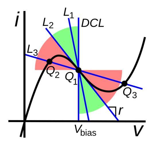
| Keywords: Negative resistance stability regions VCNR.svg characteristic curve of a voltage-controlled negative differential resistance VCNR or N type device showing regions of stable unstable and bistable load lines A DC bias voltage V<sub>bias</sub> sets the operating point Q<sub>1</sub> in the middle of the negative resistance region where the device has differential resistance Δv/Δi -r as shown by the DC load line DCL The AC load line set by the AC impedance Z facing the device passes through the Q point at a different angle depending on Z Increasing Z causes the load line to rotate counterclockwise if Z < r <font color green >green region</font> example load line L<sub>1</sub> the load line intersects the curve once at Q<sub>1</sub> so the circuit is stable if Z r line L<sub>2</sub> the net resistance of the circuit R+r 0 so the circuit is unstable and will oscillate If Z > r <font color red >red region</font> example load line L<sub>3</sub> the load line intersects the curve three times at Q<sub>1</sub> Q<sub>2</sub> and Q<sub>3</sub> The middle point Q<sub>1</sub> is unstable but the two outer operating points are stable so the circuit is bistable This biasing can be used to make flip-flops Since the device is stable for resistances below r voltage controlled negative resistances are called short-circuit stable Devices with this type of negative resistance include tunnel diodes and Gunn diodes 2012-12-26 10 55 23 own Chetvorno File Negative resistance stability regions CCNR svg cc-zero Uploaded with UploadWizard Negative resistance Device current-voltage characteristics | ||||